Joe Taylor - the Nobel Prize winning amateur radio enthusiast who developed WSJT-x - devised WSPR in 2008.
It is another machine to machine application that uses low power transmissions to determine propagation paths.
It uses a 6Hz wide FSK signal to send callsign, grid locator and signal strength (dBm).
Each frame is 120 seconds long, of which 110.6 seconds is transmission.
There is nominally a 5:1 receive:transmit ratio.
I have been using the built-in WSPR transmitter/receiver in WSJT-X.
The best reception to date on 20m was a 10mW signal from Italy! 😊
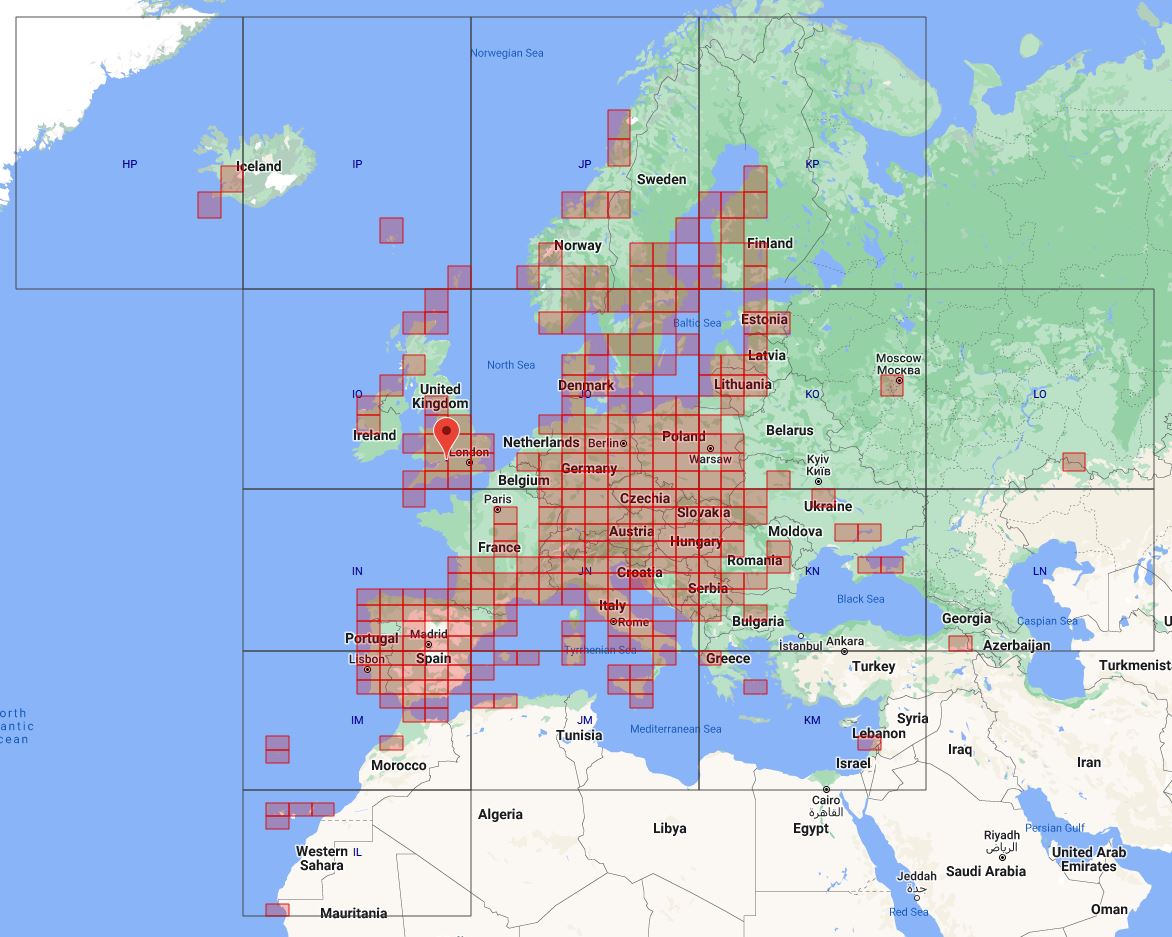
I've included a map of WSPR reporters picking up my 20m band signals where I've been using my FT817ND, running 500mW.
The longest distance reports were in Queensland and New South Wales - 10,372 miles and 10,696 miles respectively.
Click on the images to see them full size! 😉
UPDATE! - 8th February 2022
After running in to some issues regarding the transmitter 'freezing' after some 8 to 10 hours of operation, all appears to now be resolved.
I contacted Harry Zachrisson at Zachtek and appraised him of what was occurring.
After a protracted period of running the transmitter, it would just cease beaconing. The first time it happened I was able to get it to restart by removing the charger connection, plugging it back into my laptop and running the configuration software. I could see it polling the ‘visible’ satellites and then getting a positional lock.
To me, it seemed as if the device was perhaps drifting and losing the GPS position/timing signal. Harry suggested it was far more likely that the GPS antenna was picking up RFI and that, combined with the fact that I was receiving only a very weak satellite signal anyway, was the cause of the failed beaconing.
I relocated the GPS head and used double sided tape to secure it to the window glass. Then I powered up the transmitter and monitored it during a 12 hour plus period; it worked fine!
Panic over. 😃
UPDATE! - 4th February 2022
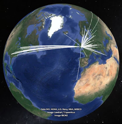
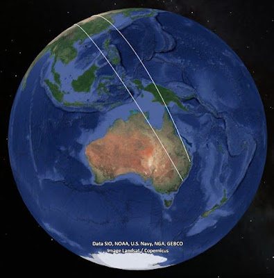
I now have the Zachtek transmitter working standalone and have collected - at the time of writing - around 6 hours of continuous data.
Here is a map - with band key - showing just where I am reaching.
Click on the image to see it full size! 😉
UPDATE! - 3rd February 2022
I now have the Zachtek transmitter working, and beaconing on the 40, 20, 15 and 10m bands.
It cycles from one band to the next and I have a 120 second break after the 4 band cycle before the process starts again.
I'm achieving some astonishing distances, bearing in mind the output power is only 200mW, or 23dBm.
When I've accrued more data, I want to try and see how each of these bands varies, propagation wise, throughout the day.
Here are some 2D plots for each of the bands.
Click on the images to see them full size! 😉
10m
15m
20m
40m